SKU: OT6683 Numero articolo: XR792 EAN: 8720828223475

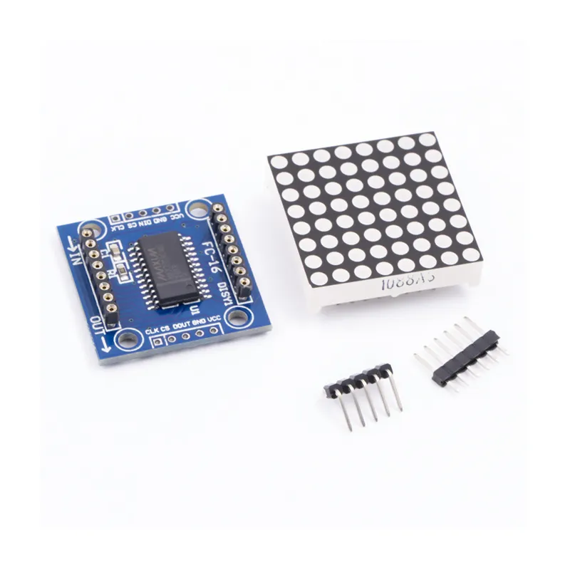
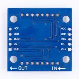
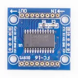
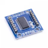
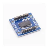
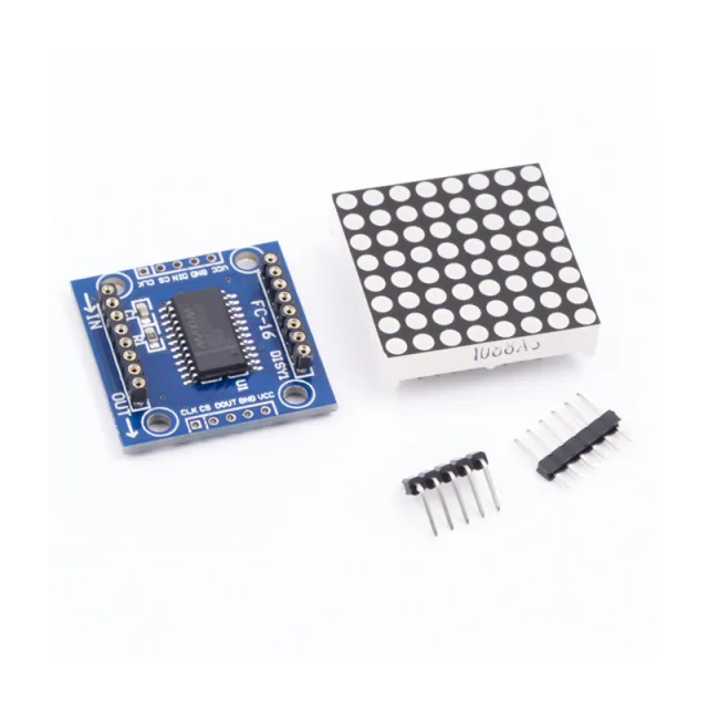
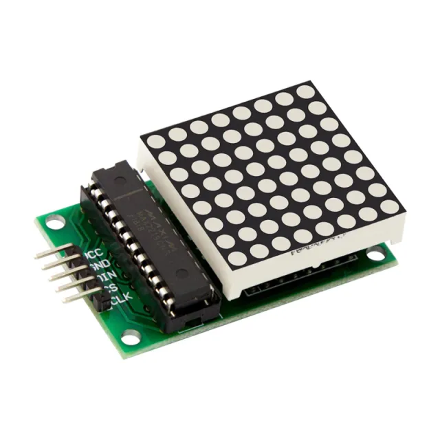
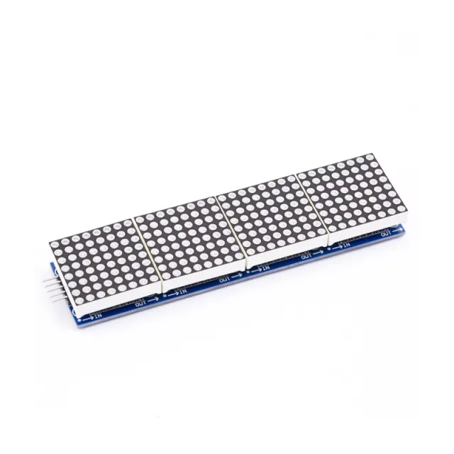
MAX7219 è un IC utilizzato per pilotare pannelli LED a catodo comune, display a 7 segmenti e indicatori di livello che comunicano tramite l'interfaccia SPI. Questa scheda ha un display LED a matrice di punti 8x8. Più moduli possono essere collegati in cascata utilizzando i connettori header.
Specifiche:
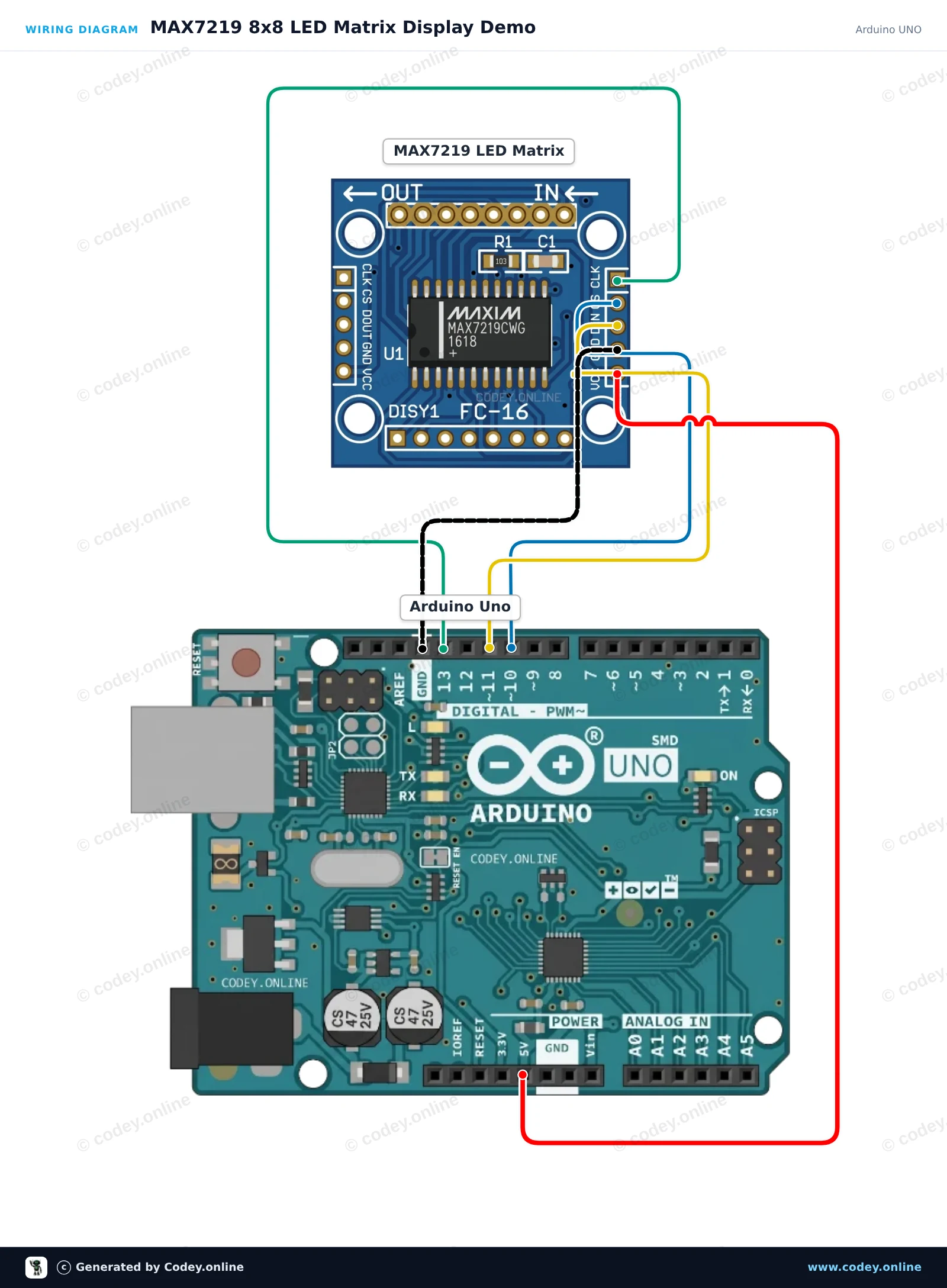
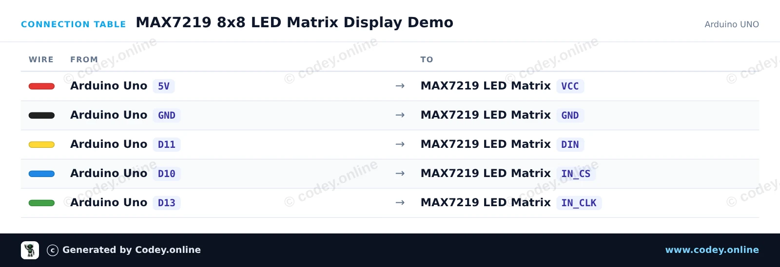
Ecco come collegare il Modulo matrice LED MAX7219 Blu a un Arduino UNO o ESP32, con uno sketch di esempio che puoi caricare subito.
Questo progetto mostra come controllare una matrice LED 8x8 utilizzando il chip driver MAX7219. Lo sketch riattiva la matrice, imposta un livello di luminosità confortevole e anima un punto rimbalzante su tutte le righe e colonne.
/*
 * ==================================================================
 *  Generated by Codey.online  —  https://www.codey.online
 * ==================================================================
 *  Project   : MAX7219 8x8 LED Matrix Display Demo
 *  Board     : Arduino UNO (arduino:avr:uno)
 *  Parts     : LED Matrix Module MAX7219
 *  Libraries : LedControl 1.0.6
 *
 *  Codey Online is an AI-powered browser IDE for Arduino and ESP32.
 *  Describe your project and Codey writes the code, draws the wiring
 *  diagram and uploads it to your board, straight from the browser.
 *  This code is free to use, modify and share, without warranty.
 * ==================================================================
 */

#include <LedControl.h>

const int DIN_PIN = 11;
const int CLK_PIN = 13;
const int CS_PIN  = 10;

// Create LedControl instance: LedControl(DIN, CLK, CS, number_of_matrices)
LedControl lc = LedControl(DIN_PIN, CLK_PIN, CS_PIN, 1);

// 8x8 bitmap for a smile icon
const byte SMILE[8] = {
  B00111100,
  B01000010,
  B10100101,
  B10000001,
  B10100101,
  B10011001,
  B01000010,
  B00111100
};

// 8x8 bitmap for a heart icon
const byte HEART[8] = {
  B00000000,
  B01100110,
  B11111111,
  B11111111,
  B01111110,
  B00111100,
  B00011000,
  B00000000
};

void drawBitmap(const byte bitmap[]) {
  for (int row = 0; row < 8; row++) {
    lc.setRow(0, row, bitmap[row]);
  }
}

void setup() {
  Serial.begin(115200);

  // Wake up MAX7219 from power-saving mode
  lc.shutdown(0, false);
  // Set medium brightness (0 to 15)
  lc.setIntensity(0, 6);
  // Clear the display
  lc.clearDisplay(0);

  Serial.println(F("MAX7219 Matrix initialized!"));
}

void loop() {
  // Display Heart
  drawBitmap(HEART);
  delay(1500);

  // Display Smile
  drawBitmap(SMILE);
  delay(1500);

  // Pixel sweep effect
  lc.clearDisplay(0);
  for (int row = 0; row < 8; row++) {
    for (int col = 0; col < 8; col++) {
      lc.setLed(0, row, col, true);
      delay(25);
      lc.setLed(0, row, col, false);
    }
  }
}Librerie necessarie: LedControl 1.0.6
Wiring diagram and example code generated by Codey.online — https://www.codey.online
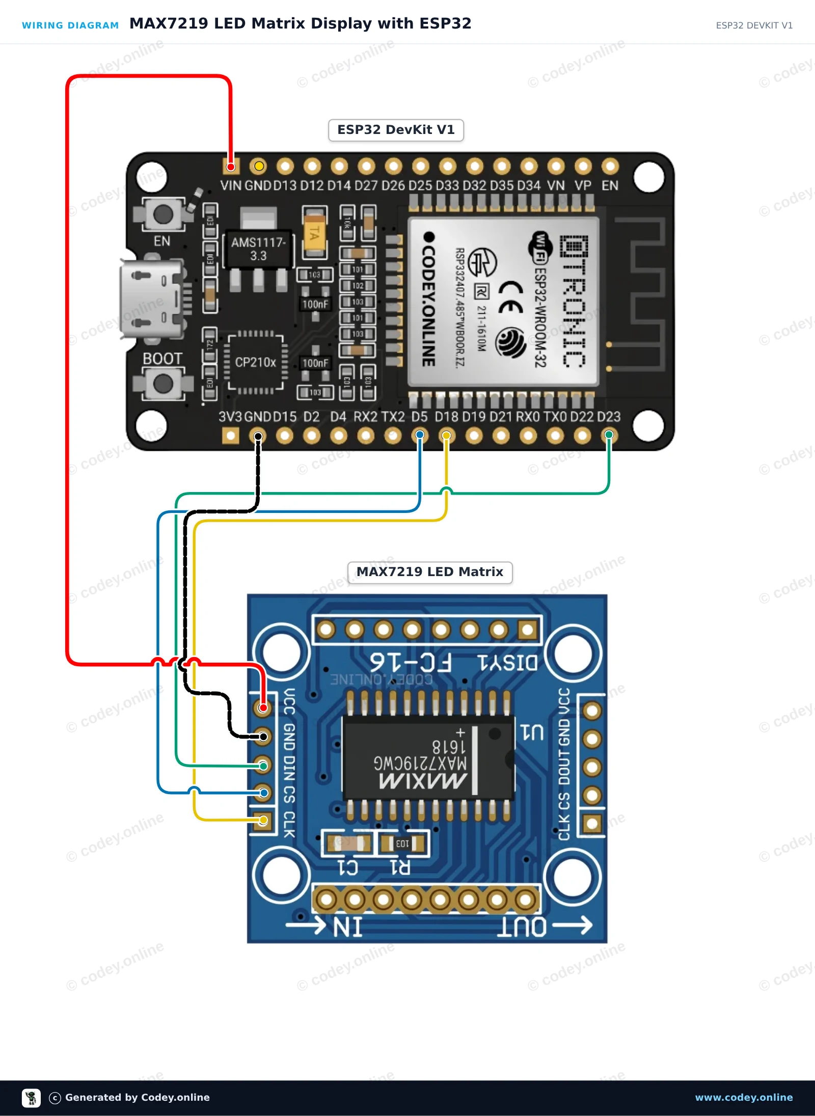
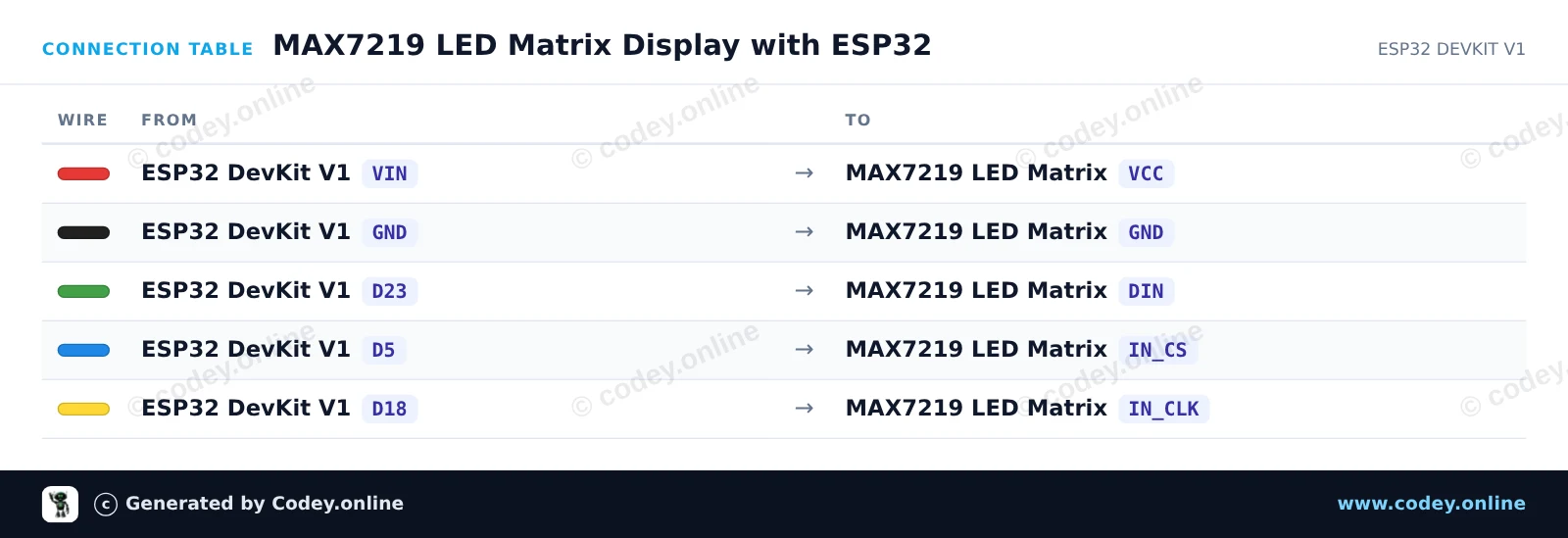
Questo progetto mostra pattern e animazioni personalizzati su un modulo matrice LED MAX7219 8x8 usando l’hardware SPI. L’ESP32 comunica con il driver tramite GPIO 23 (MOSI/DIN), GPIO 18 (SCK/CLK) e GPIO 5 (CS), alimentando il display direttamente dal pin 5V VIN.
/*
 * ==================================================================
 *  Generated by Codey.online  —  https://www.codey.online
 * ==================================================================
 *  Project   : MAX7219 LED Matrix Display with ESP32
 *  Board     : ESP32 DEVKIT V1 (esp32:esp32:esp32doit-devkit-v1)
 *  Parts     : LED Matrix Module MAX7219
 *  Libraries : none (built-in)
 *
 *  Codey Online is an AI-powered browser IDE for Arduino and ESP32.
 *  Describe your project and Codey writes the code, draws the wiring
 *  diagram and uploads it to your board, straight from the browser.
 *  This code is free to use, modify and share, without warranty.
 * ==================================================================
 */

#include <SPI.h>

const int CS_PIN = 5;

// MAX7219 register addresses
const byte REG_NOOP      = 0x00;
const byte REG_DECODE    = 0x09;
const byte REG_INTENSITY = 0x0A;
const byte REG_SCANLIMIT = 0x0B;
const byte REG_SHUTDOWN  = 0x0C;
const byte REG_DISPTEST  = 0x0F;

// Bitmaps for 8x8 graphics
const byte smile[8] = {
  0b00111100,
  0b01000010,
  0b10100101,
  0b10000001,
  0b10100101,
  0b10011001,
  0b01000010,
  0b00111100
};

const byte heart[8] = {
  0b00000000,
  0b01100110,
  0b11111111,
  0b11111111,
  0b11111111,
  0b01111110,
  0b00111100,
  0b00011000
};

void writeRegister(byte reg, byte data) {
  digitalWrite(CS_PIN, LOW);
  SPI.transfer(reg);
  SPI.transfer(data);
  digitalWrite(CS_PIN, HIGH);
}

void clearDisplay() {
  for (byte row = 1; row <= 8; row++) {
    writeRegister(row, 0x00);
  }
}

void drawBitmap(const byte bitmap[8]) {
  for (byte row = 0; row < 8; row++) {
    writeRegister(row + 1, bitmap[row]);
  }
}

void setup() {
  pinMode(CS_PIN, OUTPUT);
  digitalWrite(CS_PIN, HIGH);

  // Initialize hardware SPI (VSPI: SCK=18, MOSI=23)
  SPI.begin();

  // Configure MAX7219
  writeRegister(REG_DISPTEST, 0x00);  // Normal operation
  writeRegister(REG_SCANLIMIT, 0x07); // Scan all 8 digits/rows
  writeRegister(REG_DECODE, 0x00);    // No BCD decoding (raw matrix mode)
  writeRegister(REG_INTENSITY, 0x04); // Brightness (0x00 to 0x0F)
  writeRegister(REG_SHUTDOWN, 0x01);  // Wake up module

  clearDisplay();
}

void loop() {
  // Display smiley face
  drawBitmap(smile);
  delay(2000);

  // Display heart
  drawBitmap(heart);
  delay(2000);

  // Row sweep animation
  clearDisplay();
  for (byte i = 1; i <= 8; i++) {
    writeRegister(i, 0xFF);
    delay(100);
  }
  for (byte i = 1; i <= 8; i++) {
    writeRegister(i, 0x00);
    delay(100);
  }
}Wiring diagram and example code generated by Codey.online — https://www.codey.online





 English
  Nederlands
  Frans
Frans  Deutsch
  Español
  Suomi
Suomi  Polski
  Dansk
Dansk  Ελληνικά
  Български
  Čeština
  Hrvatski
  Aileen