SKU: OT3260 Numero articolo: NA445 EAN: 8720618231529

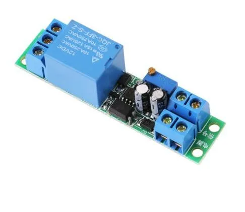
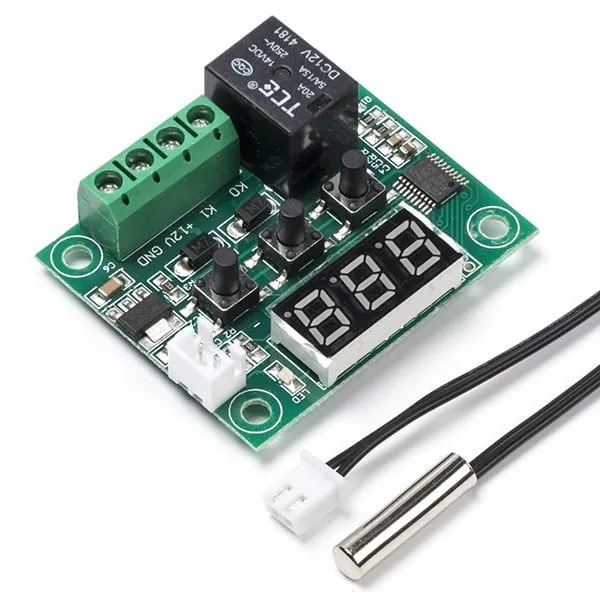
Questo modulo relè a ritardo temporale funziona a 12V e può essere impostato tramite il trimmer.
Tensione di funzionamento: DC 12V
Consumo di corrente (quando attivato): ~46mA
Tensione massima attraverso il relè: 30VDC o 250VAC
Corrente massima attraverso il relè: 10A
Ritardo regolabile tra 0.1 e 25 secondi
Per istruzioni e uno schema di collegamento abbiamo a vostra disposizione la Guida rapida OTRONIC per il modulo relè con ritardo temporale regolabile 12V.
Istruzioni:
Questo modulo relè OTRONIC® con ritardo temporale regolabile ha un ritardo regolabile per lo spegnimento (rilascio).
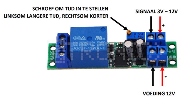
Test del relè
È possibile testare il tempo impostato del relè senza un comando esterno.
Collegare un'alimentazione da 12V a VCC e GND (alimentazione). Senza segnale il relè eseguirà una sola volta il
ritardo temporale. È possibile sentirlo dal clic del relè.
Utilizzare il trimmer per regolare il tempo. In senso antiorario per un tempo più lungo e in senso orario
per un tempo più breve.
ATTENZIONE: Sono necessarie più rotazioni del trimmer per regolare il tempo.
Dimensioni
Lunghezza: 6,68cm
Larghezza: 1,6cm
Altezza: 1,68cm
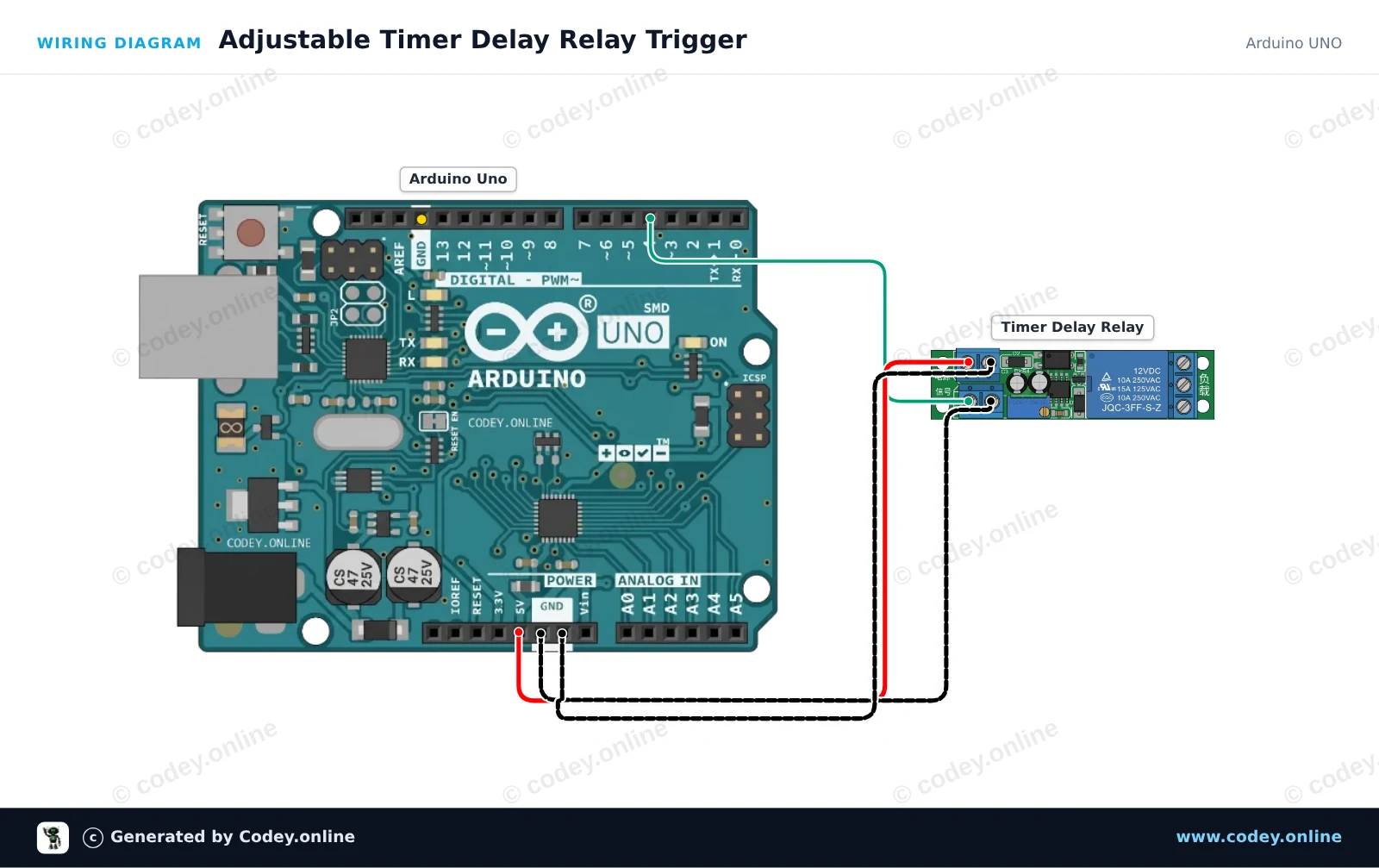
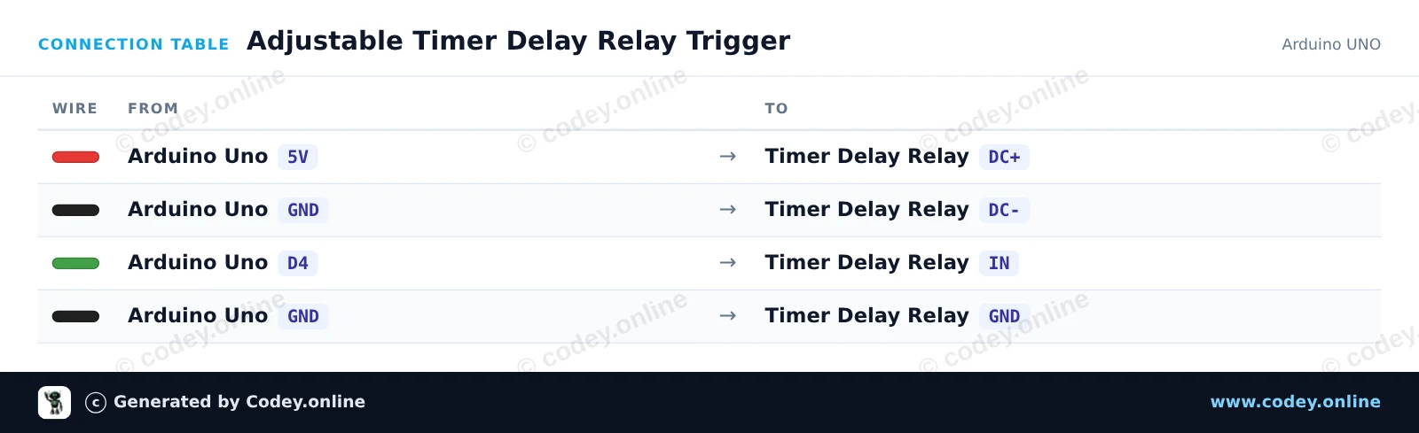
Ecco come collegare il Modulo relè con ritardo temporale regolabile 12V a un Arduino UNO o ESP32, con uno sketch di esempio che puoi caricare subito.
Questo progetto mostra come attivare un modulo relè con ritardo timer regolabile utilizzando un Arduino Uno. L’Arduino invia un breve impulso dal pin digitale 4 al pin di trigger IN, attivando il ciclo di ritardo timer integrato. Regola il potenziometro sul modulo relè per modificare la durata dell’attivazione del relè.
/*
 * ==================================================================
 *  Generated by Codey.online  —  https://www.codey.online
 * ==================================================================
 *  Project   : Adjustable Timer Delay Relay Trigger
 *  Board     : Arduino UNO (arduino:avr:uno)
 *  Parts     : DC 12V adjustable timer delay, time delay relay turn off switch module time relay time switch 0~25sec for smart home, automatic control
 *  Libraries : none (built-in)
 *
 *  Codey Online is an AI-powered browser IDE for Arduino and ESP32.
 *  Describe your project and Codey writes the code, draws the wiring
 *  diagram and uploads it to your board, straight from the browser.
 *  This code is free to use, modify and share, without warranty.
 * ==================================================================
 */

// Timer Delay Relay Module Demo
// Sends a trigger pulse to start the module's countdown delay.

const int triggerPin = 4;

void setup() {
  pinMode(triggerPin, OUTPUT);
  digitalWrite(triggerPin, LOW);

  Serial.begin(115200);
  Serial.println(F("Timer Delay Relay Demo Initialized."));
}

void loop() {
  Serial.println(F("Triggering relay delay cycle..."));

  // Send a 200 ms HIGH pulse to trigger the module
  digitalWrite(triggerPin, HIGH);
  delay(200);
  digitalWrite(triggerPin, LOW);

  Serial.println(F("Trigger sent. Waiting for delay cycle to complete..."));

  // Wait 10 seconds before triggering the next cycle
  delay(10000);
}Wiring diagram and example code generated by Codey.online — https://www.codey.online
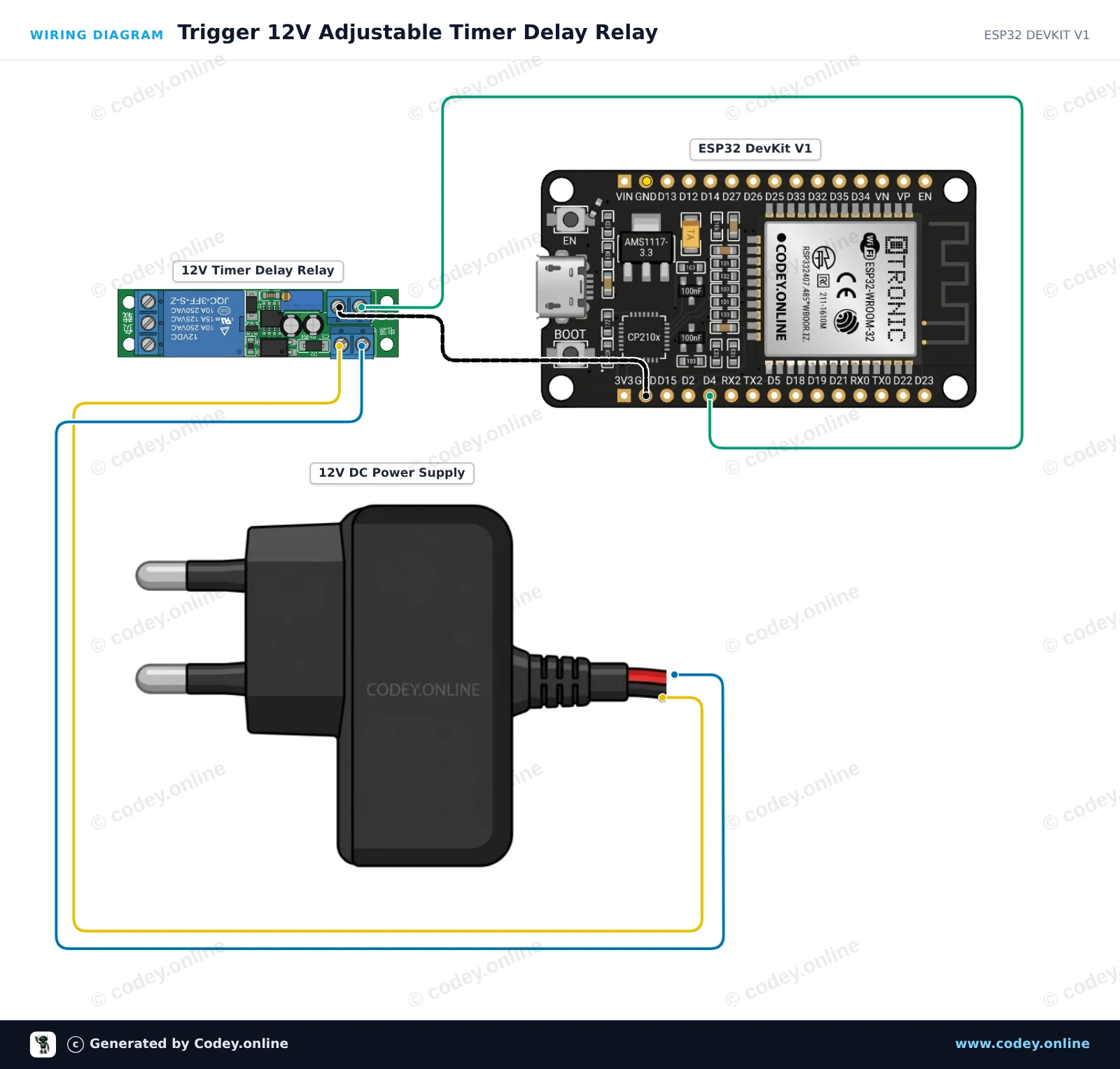
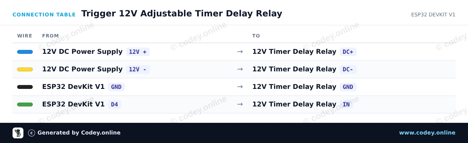
Questo progetto mostra come attivare un modulo relè temporizzato 12V regolabile usando un ESP32. L’ESP32 invia un breve impulso di trigger per avviare il conto alla rovescia, e il relè rimane eccitato per la durata impostata dal potenziometro onboard (0 to 25 seconds).
/*
 * ==================================================================
 *  Generated by Codey.online  —  https://www.codey.online
 * ==================================================================
 *  Project   : Trigger 12V Adjustable Timer Delay Relay
 *  Board     : ESP32 DEVKIT V1 (esp32:esp32:esp32doit-devkit-v1)
 *  Parts     : DC 12V adjustable timer delay, time delay relay turn off switch module time relay time switch 0~25sec for smart home, automatic control
 *  Libraries : none (built-in)
 *
 *  Codey Online is an AI-powered browser IDE for Arduino and ESP32.
 *  Describe your project and Codey writes the code, draws the wiring
 *  diagram and uploads it to your board, straight from the browser.
 *  This code is free to use, modify and share, without warranty.
 * ==================================================================
 */

// Pin connected to the IN trigger pin of the timer relay module
const int TRIGGER_PIN = 4;

void setup() {
  Serial.begin(115200);
  pinMode(TRIGGER_PIN, OUTPUT);
  digitalWrite(TRIGGER_PIN, LOW);

  Serial.println("ESP32 12V Timer Delay Relay Module Initialized");
  delay(1000);
}

void loop() {
  Serial.println("Sending trigger pulse...");

  // Send a 200 ms pulse to activate the timer
  digitalWrite(TRIGGER_PIN, HIGH);
  delay(200);
  digitalWrite(TRIGGER_PIN, LOW);

  Serial.println("Triggered! The relay will remain active for the duration set by the potentiometer.");

  // Wait 15 seconds before triggering the next cycle
  delay(15000);
}Wiring diagram and example code generated by Codey.online — https://www.codey.online






 English
  Nederlands
  Frans
Frans  Deutsch
  Español
  Suomi
Suomi  Polski
  Dansk
Dansk  Ελληνικά
  Български
  Čeština
  Hrvatski
  Aileen