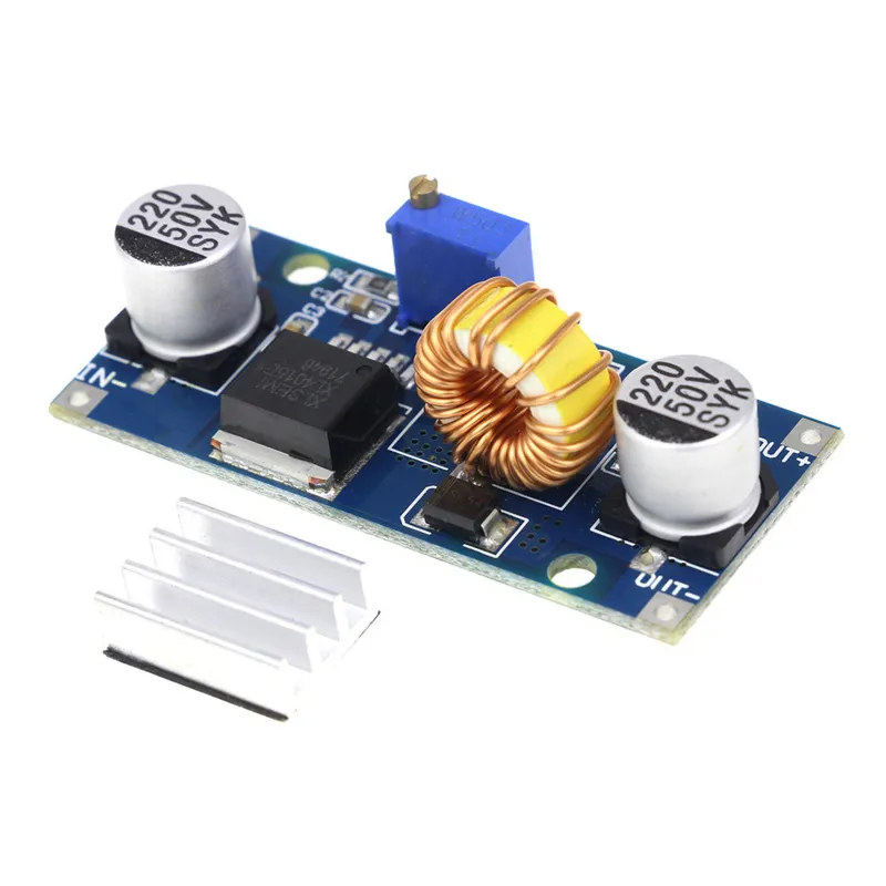
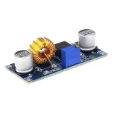
SKU: OT2004-A113 Numero articolo: AA270 EAN: 8179262862427

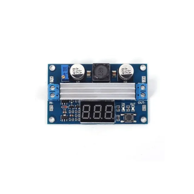
Tensione di ingresso 4-38VDC
Tensione di uscita 1.25-36VDC, regolabile
Potenza di uscita 0-5A, con protezione da cortocircuito in uscita.
Uscita massima 75W con protezione termica
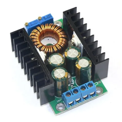
Incluso dissipatore di calore fornito non montato. Può essere fissato tramite la striscia 3M applicata.
Afmetingen
Lengte: 5,4cm
Breedte: 2,45cm
Hoogte: 1,7cm
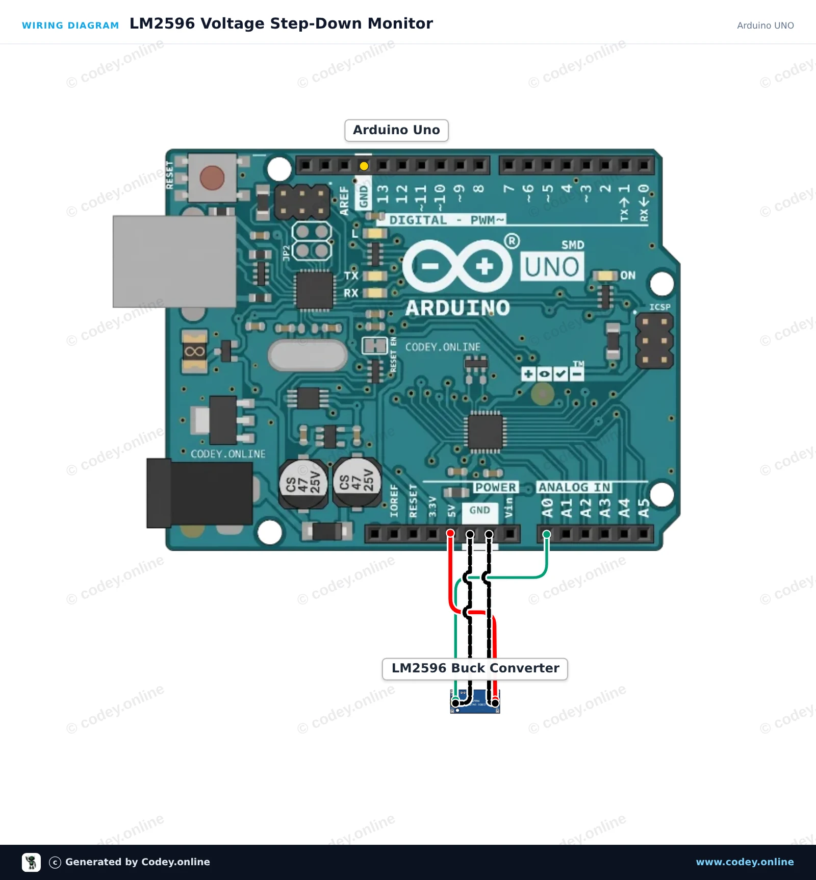
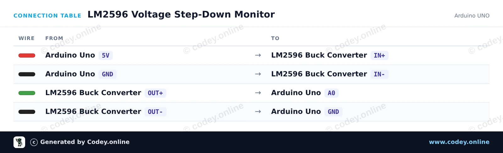
Ecco come collegare il Modulo step-down regolabile 4~38V 5A 96% Alta efficienza XL4015 a un Arduino UNO o ESP32, con uno sketch di esempio che puoi caricare subito.
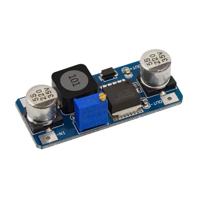
Questo progetto alimenta il modulo step-down LM2596 dalla linea 5V dell'Arduino e misura la sua tensione di uscita regolata sul pin analogico A0. Regola il potenziometro integrato con un piccolo cacciavite per osservare le variazioni di tensione in tempo reale stampate nel Serial Monitor (mantieni l'uscita sotto 5V).
/*
 * ==================================================================
 *  Generated by Codey.online  —  https://www.codey.online
 * ==================================================================
 *  Project   : LM2596 Voltage Step-Down Monitor
 *  Board     : Arduino UNO (arduino:avr:uno)
 *  Parts     : Adjustable Step-down Module 3-40VDC 1.5-35VDC LM2596
 *  Libraries : none (built-in)
 *
 *  Codey Online is an AI-powered browser IDE for Arduino and ESP32.
 *  Describe your project and Codey writes the code, draws the wiring
 *  diagram and uploads it to your board, straight from the browser.
 *  This code is free to use, modify and share, without warranty.
 * ==================================================================
 */

const int voltagePin = A0;

void setup() {
  Serial.begin(115200);
  while (!Serial) {
    ; // Wait for serial port to connect
  }
  Serial.println(F("LM2596 Step-Down Voltage Monitor"));
  Serial.println(F("Turn the onboard trimmer to adjust the output voltage (0-5V)."));
}

void loop() {
  int rawValue = analogRead(voltagePin);
  float voltage = rawValue * (5.0 / 1023.0);

  Serial.print(F("ADC Value: "));
  Serial.print(rawValue);
  Serial.print(F(" | Output Voltage: "));
  Serial.print(voltage, 2);
  Serial.println(F(" V"));

  delay(500);
}Wiring diagram and example code generated by Codey.online — https://www.codey.online
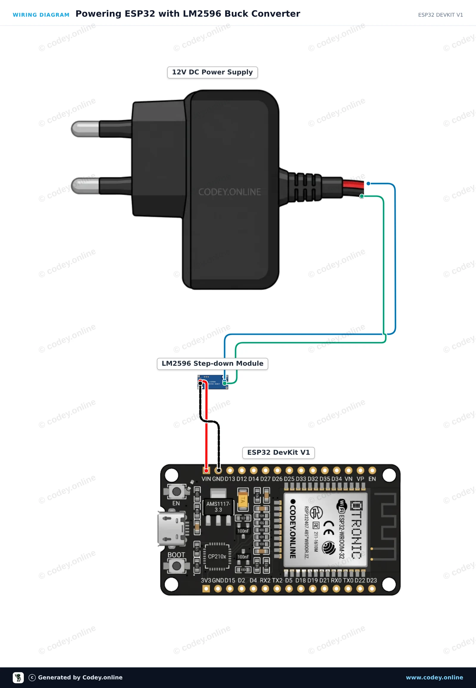
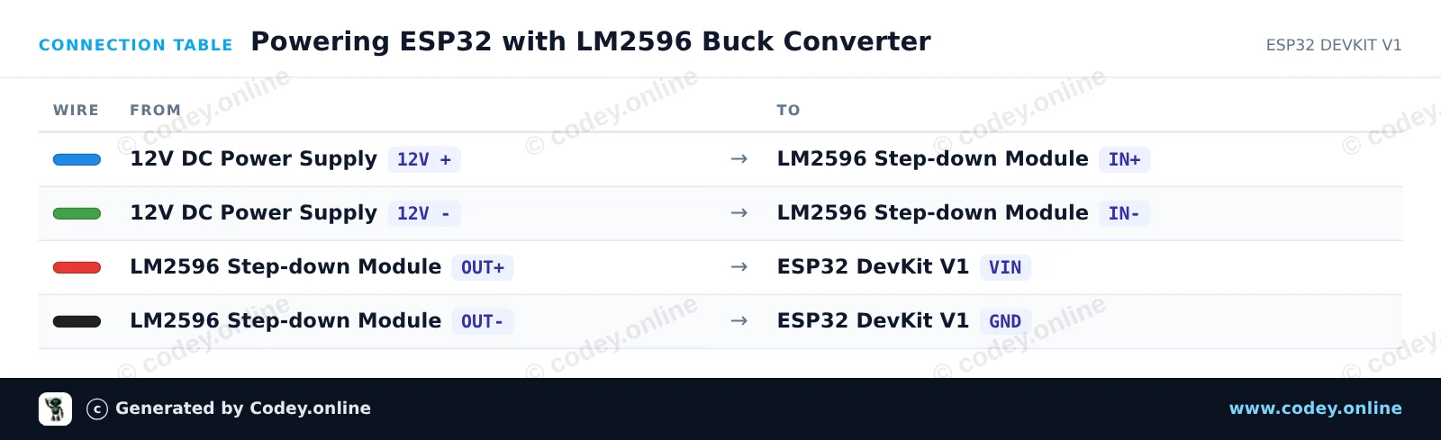
Prima di collegare l'ESP32, usa un multimetro per regolare il potenziometro trimmer dell'LM2596 finché OUT+ non legge esattamente 5.0V. Il modulo abbassa in modo efficiente l'ingresso 12V a un'uscita stabile da 5V per alimentare l'ESP32 tramite VIN e GND. Una volta collegato, l'ESP32 si avvia, fa lampeggiare il LED di stato onboard ed emette messaggi heartbeat tramite Serial.
/*
 * ==================================================================
 *  Generated by Codey.online  —  https://www.codey.online
 * ==================================================================
 *  Project   : Powering ESP32 with LM2596 Buck Converter
 *  Board     : ESP32 DEVKIT V1 (esp32:esp32:esp32doit-devkit-v1)
 *  Parts     : Adjustable Step-down Module 3-40VDC 1.5-35VDC LM2596
 *  Libraries : none (built-in)
 *
 *  Codey Online is an AI-powered browser IDE for Arduino and ESP32.
 *  Describe your project and Codey writes the code, draws the wiring
 *  diagram and uploads it to your board, straight from the browser.
 *  This code is free to use, modify and share, without warranty.
 * ==================================================================
 */

// LM2596 Step-Down Buck Converter ESP32 Power Demo
// Note: Always adjust LM2596 output to 5V before connecting to VIN!

const int LED_PIN = 2; // Onboard LED

void setup() {
  Serial.begin(115200);
  pinMode(LED_PIN, OUTPUT);

  Serial.println("LM2596 Step-Down Buck Converter Demo");
  Serial.println("ESP32 successfully running on regulated 5V power!");
}

void loop() {
  // Turn LED on
  digitalWrite(LED_PIN, HIGH);
  Serial.print("Uptime: ");
  Serial.print(millis() / 1000);
  Serial.println(" s | Power Status: OK (LED ON)");
  delay(500);

  // Turn LED off
  digitalWrite(LED_PIN, LOW);
  delay(500);
}Wiring diagram and example code generated by Codey.online — https://www.codey.online





 English
  Nederlands
  Frans
Frans  Deutsch
  Español
  Suomi
Suomi  Polski
  Dansk
Dansk  Ελληνικά
  Български
  Čeština
  Hrvatski
  Aileen